Wireless Épée Scoring System
Applied Engineering research project, grades 10-12
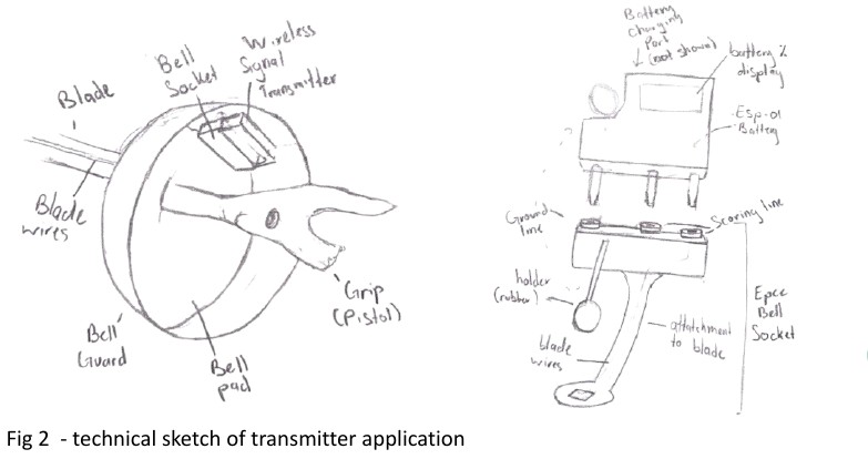
In épée fencing, a touch is registered when the tip of the blade is pressed, and the signal travels through a chain of wires to the scoring machine. This project replaces that chain with a compact wireless transmitter that plugs into the blade and an identical receiver at the scoring machine.
The problem
The current system runs from the scoring machine to a reel box at each end of the strip, then through a body cord under the fencer's jacket and sleeve, and finally into a socket in the bell guard. With so many connections, failures are common and hard to locate. The reel box gets unplugged, the cord shifts under the jacket, and the resulting delays and disputes slow down bouts at tournaments.
Wireless systems have been tried before, but were dropped for weak signals, interference from nearby bouts, short battery life, and the need for a technician. The goal here is a cheap, reliable add-on that works with existing épées and can run alongside the wired system.
Requirements
The attachment has to feel like the traditional wired connection, so fencers notice no difference.
- Matches the 2.92 V measured on a standard blade
- 10-20 ms response time, like a wired blade
- At most 20 g and 40x40x15 mm, to fit in the bell guard
- At least 36 hours of battery life, easy to recharge or replace
- Reliable range of 20 m or more, even with high interference
- A secure, durable and comfortable attachment
Choosing a radio
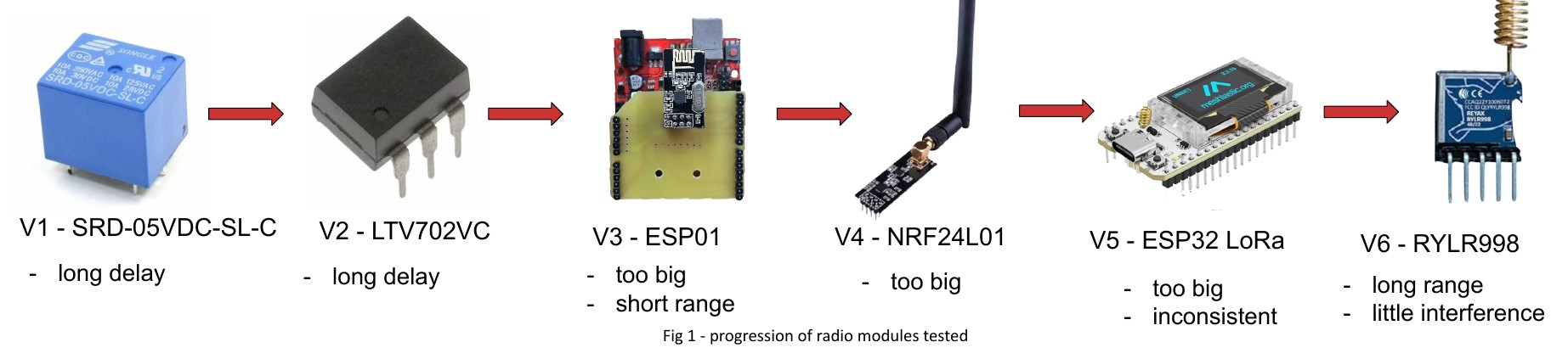
Six radio modules were tested for response time, range, size and reliability. The relay and optocoupler were too slow, the ESP-01 and NRF24L01 too large or too short-ranged, and the ESP32 LoRa too large and inconsistent. The REYAX RYLR998 LoRa module met every requirement.
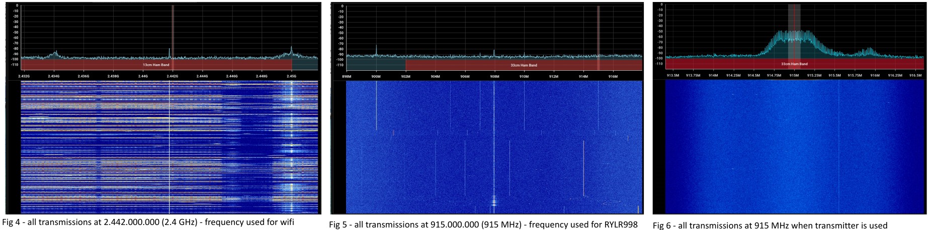
It transmits at 915 MHz instead of the crowded 2.4 GHz band used by wifi. Spectrum captures at both frequencies confirmed that the 915 MHz transmission is clear and distinguishable, with very little noise.
The prototype
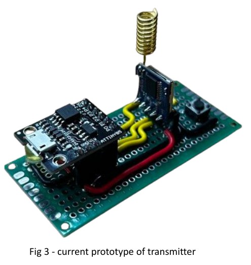
The current transmitter pairs a Digispark ATtiny85 microcontroller, chosen for its small size and low power use, with the RYLR998 radio, soldered together on a PCB. It is designed to plug directly into the bell guard socket in place of the body cord. The next steps are a 3D-printed case, a battery that is easy to swap, a matching receiver for the scoring machine, and testing in real bouts.
Circuit design in KiCad
The transmitter electronics are drawn as a schematic in KiCad, as the basis for a custom PCB. It is built around the ATtiny85 microcontroller, with a five-pin connector for the radio module, a 3.3 V regulator (AP2112K-3.3) to power the electronics from the battery, and a battery charging controller (MCP73811) so the battery can be recharged on the board. The parts are small surface-mount components, to help the board stay within the size limit of the bell guard attachment.
- Microcontroller: ATtiny85 (SOIC-8)
- Radio: 5-pin connector for the REYAX RYLR998 module
- Power: AP2112K-3.3 regulator and MCP73811 charge controller
- Other: 2x3 pin header, battery terminal, mounting holes
Plan
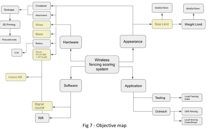
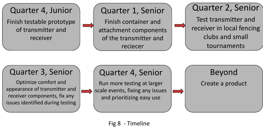
The work is organized into hardware, software, appearance and application, as shown in the concept map. Over senior year the plan is to finish the container and attachment, optimize comfort and appearance, test in local fencing clubs and small tournaments, and then run larger-scale tests.
Documents and links
Research paper (PDF) Research poster (PDF) Concept map (PDF) KiCad schematic on GitHub All project files on GitHub